WARNING
All of the information below was added gradually and only represents a portion of the actual story;
For this reason what you find here might be outdated and not completely up to what we're actually doing at the moment.
See the Story section for more details.
ALSO this website uses a summary for navigating, you can check it on your left!
What is the "The Army" project?
The Army is a school project born out of the HoPE (Hands on Physics Experience) initiative, proposed by our school in collaboration with the Massachusetts Institute of Technology (MIT). The goal of the project is to develop a mechanical arm that can be remotely controlled over long distances via an internet connection through a wereable glove.
Planning
After brainstorming basic ideas, we decided to adapt an old school project, which consisted of a simple motorized gripper, into something much more functional: a complete arm, including an elbow, entirely based on Arduino and its ecosystem. The addition of Arduino Cloud allows communication between the controls and the arm, even across entire continents, and also Smart Home integrations like Alexa or Google Home.
Our six-person team divided the main tasks in:
- Communication
- 3D Modeling
- Assembly
- Programming
In every parts of the project the different teams interacted and some of them even helped the other by just for example even optimizing their codes.
Gathering Resources for the Initial Sketch
The 3D modeling team immediately began searching for a base model to work from, finding it here. Meanwhile, the communication team researched how to use Arduino Cloud and collaborated with the programming team to transmit initial inputs through Arduino Cloud. This enabled the physical movement of servo motors provided by school funds.
Developing the First Prototype
Using the school's 3D printer, the modeling team completed the printing of all essential parts, enabling the assembly team to begin their work. Compared to the original model, some parts were refined and modified using Blender. Notably, the last 3D-printed parts were combined to improve grip strength.
The communication and programming teams wrote the necessary code for data transmission between two Arduinos connected via Arduino Cloud. This led to a great success of connecting the two Arduinos via Wi-Fi.
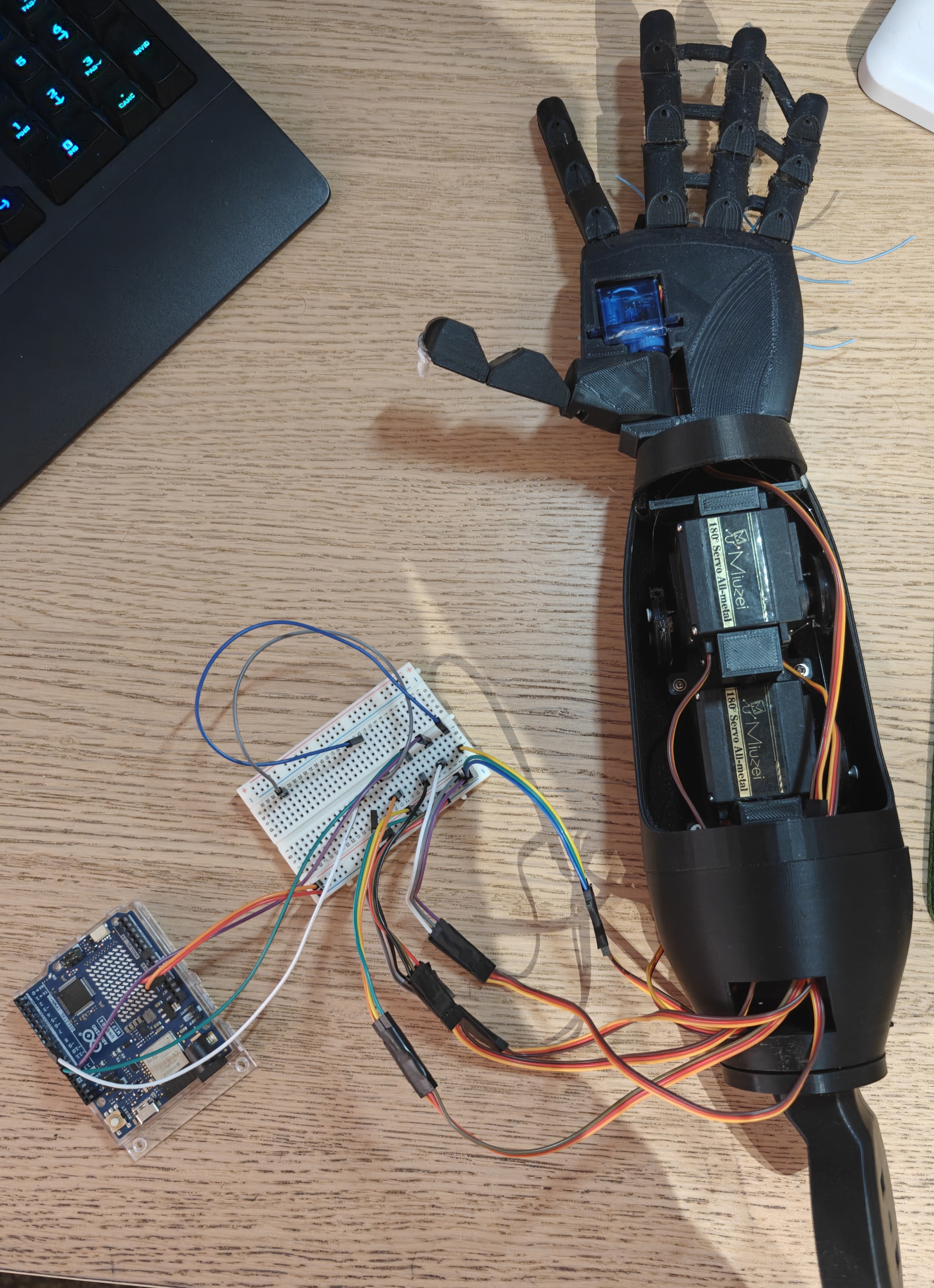
Here's the physical appearance of our proud final prototype v1 (unfortunately we couldn't finish in 8 months the palm, wrist and elbow, but they're not hard to do now that we've got the hang of it):
First Tests
Besides all the test ran by the project here the communication and programming teams, during a school celebration event, were able to run the first tests and show it off to our professors, and it actually started working!
The tests were simple: since at the time we didn't have long cables or breadboards we could move only one finger per time.. and the index finger worked! Across the room the two teams started moving the finger through a potentiometer.
See the Coding section for more details.
Next steps
Besides implmenting palm, wrist and elbow, we'll also try to make the arm itself prettier and finalize the glove that should move the arm.
Credits
| Person | Work |
|---|---|
| NexIsDumb | Coding of connection between the arduinos, coding reviews, coding optimizations, website, documentation, GitHub organization stuff, helps the other members with coding optimizations and more |
| Matte549 | Internal base code for the devices and circuits |
| Turkiztron | Internal base code for the devices, 3D models of the devices, their printing and circuits |
| Tindaniel706 | 3D models of the devices, 3D models edits, documentation and presentation |
| Leggend | Aspect side of the project while also helping the others and 3D models editing |
Detailed STEP by STEP workflow of the group project "The Army"
An exciting start: Edward Moriarty's Meeting
On our first day at the Hope afternoon meeting (23/10/2024), we were greeted by Ed and a team of Italian tutors who helped us get everything started and decide which projects were worth the effort. After setting up our initial groups (based on everyone’s preferences), Ed himself, and sometimes even other people from the MIT Institute, started talking to each group on different occasions (both in person and via calls) to share his experience and thoughts on what he believed was the correct course of action for the things we wanted to make. They would often provide us with extremely valuable information to pursue something that was actually feasible with our resources—essentially making sure we wouldn’t waste any time or money.
The First Ideas: Brainstorm Phase
The first thing we did was organise exactly what we needed to figure out and in what order. Since our final objective was to create a robotic 3D-printed arm that could be controlled wirelessly, we immediately began searching for a suitable 3D model of the arm and also started learning the basics of Arduino, as not everyone was already an expert in this regard.
After that, we:
- Set up a GitHub repository for everyone to collaborate more efficiently.
- Conducted numerous tests on the connection side of things (all of which are available on GitHub!) and, around the Christmas period, decided to use Arduino Cloud for the connections between boards.
- Printed all the necessary 3D parts with standard PLA filament and adjusted some of them to our needs using Blender (such as connecting the three fingers together for a stronger grip, an idea that originated from Ed).
- Assembled the parts and installed our first servo-motors (the actual moving parts behind the fingers).
- Programmed the base to make the servo-motors respond to manual input.
- Searched for a way to integrate Arduino with brainwaves (since we initially wanted to translate those waves into movements).
The Intermediate Work Phase
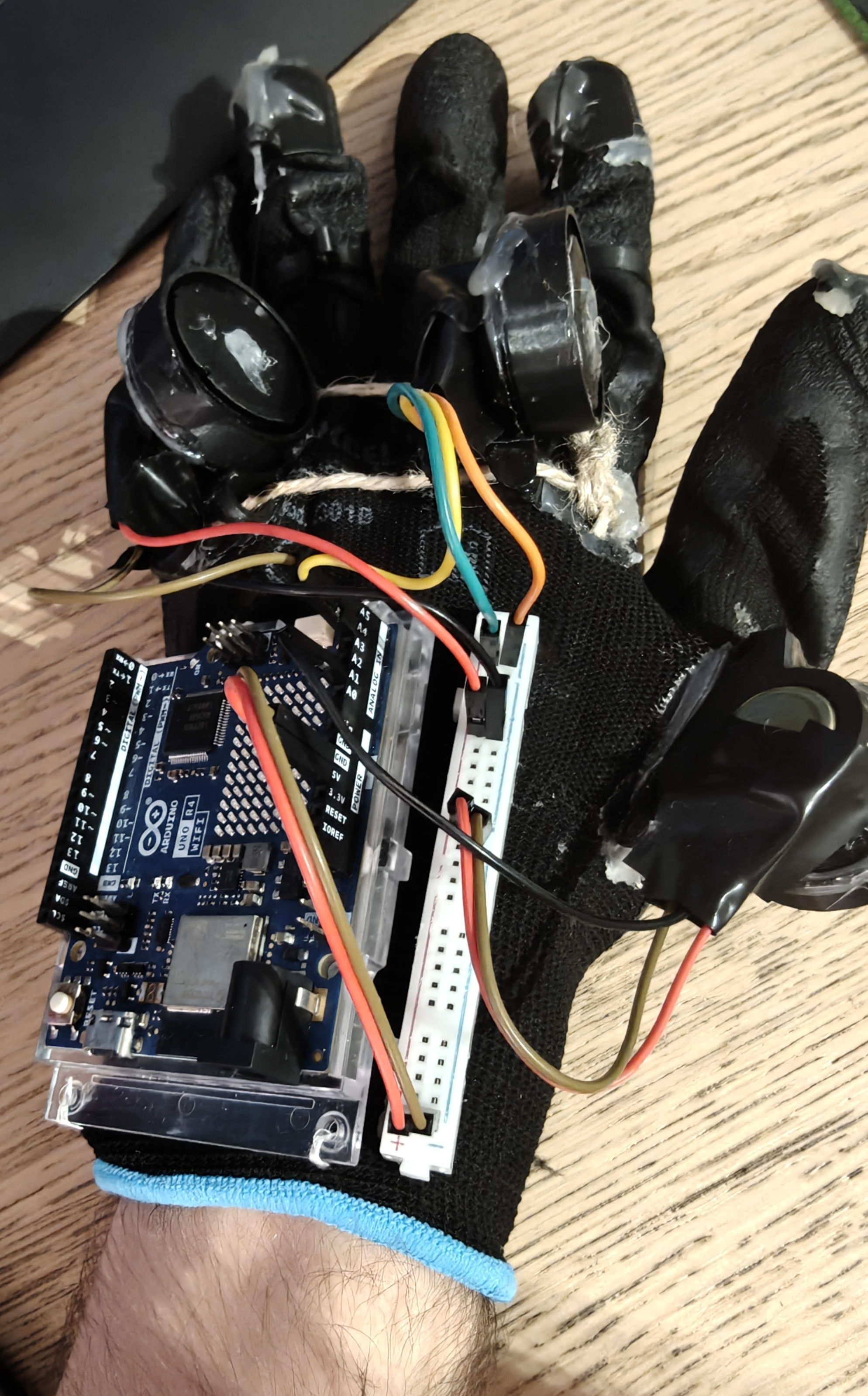
With the project's foundations now in place, we felt ready to take a step forward and purchase the necessary sensor to use brainwaves within the Arduino environment. The problem was, aside from being terribly expensive, this sensor had practically no documentation and had received many negative reviews for its fragility. However, it was still the only remotely usable option for the project... but with limited resources and with us not being able to risk spending all that money on a crucial component of dubious quality, we consulted with each other to decide whether to change direction and opt for a simpler control system that could be created in less time or not. We settled to use a glove filled with flex sensors connected to an Arduino board, which would send all inputs to the cloud, set up to be dynamically used by the robotic arm to move all its parts.
To test the new method, we programmed the second board, identified as "glove", and initially connected just one flex sensor to check if it worked properly. From this test, it quickly became apparent that our flex sensors were deteriorating too easily and giving inaccurate readings, resulting in movements of the arm that were misaligned with the actual movement. Knowing this, we had two options:
- Search for significantly higher-quality flex sensors, which would increase the total cost of the project.
- Change the method of movement measuring with something else.
Meanwhile, thanks to our personal 3D printer (the school’s one had unfortunately broken), we completed and assembled all the parts of the arm, including the internal servo-motors, the joint for a potential shoulder, the three joined fingers, internal wires, the external casing, and the internal board responsible for controlling all the servo and mini servo-motors.
Apart from a few other modifications we still needed to make later on an aesthetic level, the arm itself was considered practically finished since we had already completed all the programming. Now, we had to start thinking again about how we wanted the user to control its movement.
By the end of January (2025), Ed’s team returned to assist all the groups at the institute. Taking advantage of this opportunity, we asked the experts for a more efficient way to obtain numerical values from the glove’s movement (thus discarding the flex sensors). In response, Ed redirected us to the YouTube channel of Lucas Pope, a genius who had managed to create very cheap virtual reality gloves. By researching his project and, most importantly, observing the design of his gloves, we realised that all we needed were simple potentiometers and some wires.
We took the potentiometers, attached them to the glove and its board, and finally completed the control system. All that was left was to test everything thoroughly and refine the final product, at least for the robotic arm itself. Naturally, we also needed to finish the wiki website hosted on github (this site).
Testing Phase and Finalisation
Once we had a fully functional arm and the first prototype of the glove with the potentiometers, we tried to move the first finger completely wirelessly. In front of our professors and friends, who were anxiously waiting to see this promised remote-controlled arm, we managed to move the ring finger in real-time without any issues or significant delays. We had achieved our goal!
From that moment on, we dedicated all our subsequent meetings to perfecting and adding extra features or improving the design of our project's wiki website.
We will do our best to improve our product as much as possible, starting with getting the entire hand to move smoothly! And maybe we’ll even think about making the design a bit more appealing, since right now it looks more like a Frankenstein creation made of hot glue, plastic, rope, and circuits. But that’s another story that we will fix later.
The UPC Space Program Collaboration
Once we went to MIT in Boston for the 2025 edition of EDW and showcased our project, a Barcellona professor came to us and asked to get in contact with one of her old students: Joel Garcia. Joel was working on an amazing project for his university: The UPC Space Program and with it, a space rover prototype. Starting from this, we spent an entire evening to think about a possible collaboration between thir Rover and our Glove/Arm, and so we had the idea: Moving their Rover with our Glove! On the same evening we stayed in a Discord voice channel with Joel to find ways to make the idea possible and after some hours we were able to make it work!
Based on how we moved the Glove's Index finger, the Rover would move Back and Forth, while it'd move Left and Right based on the Middle finger's movements.
And the next day we were able to produce a video out of it!
{% embed youtube id="1HUfG7jVaCY" %}
Such a wonderful experience!
ALL RESOURCES USED IN THE PROJECT
Below is the complete list of parts, components and tools we used so that anyone can replicate what we did.
This is NOT a tutorial, it's only a LIST. If you'd like instructions and all of the repositories where our projects and this one too are stored, go to Coding.
Electrical parts
Besides a decent 3d printer, hot glue, a general Nylon Glove, general strings and some other generic tools, you'll also need:
| ID | Part name (you can also find these parts easily in other non italian stores) | Part number | Quantity |
|---|---|---|---|
| B1 | Breadboards pack | B00VXC5J3M | 1 (2 if not as pack) |
| C2 | Breadboard cables pack | B01N40EK6M | 1 (at least 12 if not as pack) |
| P1 | 10k Potentiometers pack | B0D6XZ2875 | 2 (4 or 5 if not as pack, depends if you'd like to do the elbow too) |
| F1 | 500g Flex Sensor | B08B88W3H5 | 1 |
| S1 | 15kg Servomotors pack | B0C4T73SMB | 1 (4 if not as pack) |
| S2 | Mini Servomotor | B0BBR4RB5H | 1 |
| R4 | Arduino UNO R4 WiFi | ABX00087 | 2 |
Digital Sources and Tools
We used Blender to edit and Ultimaker Cura for slicing all the 3D models used.
Sometimes we used Arduino Ide but later on switched entirely to Arduino Cloud for coding (so we could also use and test wireless data transfers).
You can find all of the used 3D models used here.
We had the idea of using potentiometers instead of flex sensors for all the fingers from Lucas VRTech's video.
ALL CODING RELATED INFORMATIONS OF THIS PROJECT
Below are some coding notes and considerations.
If you would like to look at the whole project files and more, you can visit our GitHub organization and our main project repository where everything related to Remote Arm project (coding related and more) is saved and documented.
I'd suggest to also take a look at all the tests I made before starting with the arm project directly, just to get known with Arduino better; trust me some of them were really cool to look at!
Splitting the work
As we said before, we divided the coding tasks into 2:
| Physical coding team | Connection / Cloud coding team |
|---|---|
| Matte549 and Turkiztron | NexIsDumb |
The Physical coding team would have worked on the physical base (like fingers movements), the Connection / Cloud coding team would have worked on figuring out the best way to connect remotely the two Arduinos and also code it.
As the physical base group proceeded, the connection team instead thought at first to buy a server and a domain to make the two boards communicate, it wasn't hard to code either but issues like "what would happen if you stopped paying yearly for the server" popped up: if we wanted something to be working forever we had to find another way.
While searching online we found out about Arduino Cloud and it being free and compatible with our R4 boards.
After the connection ran some tests to understand how it worked, they immediately understood that it was the best option.
How it developed
As the physical base group started using the servos and flex libraries to complete it whole, the connection team made two Arduino Could "Things"; the Glove Thing and the Arm Thing and linked the two arduinos to them, using at first a single sycnhronized variable that was a string containing all the needed finger and body parts movement degrees splitted by a comma through a specific split code: at first they thought this would make it faster to send since they were less Bits, the arm would split and get the right values out of the string.
Although after a while they realized that it was annoying understanding on which position of the string were the right degree values of each arm part and that using multiple integrer values wouldn't made the project lag at all and so they went for that way.
How it ended
Once every group finished their coding part, NexIsDumb started merging everything together and separating the right way the Arm and Glove code and optimize it too a little bit. With Matte549's help they also started to find the right finger max and min values for making it work best.
The final big showcase and test of the project was made at NexIsDumb's finals: during the last exam he started moving with Matte549's help the arm perfectly fine through the glove and all professors were completely amazed!
Unfortunately we couldn't make it in time to add the palm, elbow and wrist, but they aren't hard to add since the code for them is already there.
More coding notes
For getting the flex sensors and potentiometers values, the glove's code uses an analogRead function to get from the desired pin a value between 0 and 1023. To make sure this number was translated into integrer angles, we've used a map function setting specific min and max of the angles (that the program would have used based on analogRead's raw number) based on how we've placed the servomotors in the arm, this took bunch of tries as you have to look on their position and rotation.
Here's an example:
indexDeg = map(analogRead(indexPin), 0, 1023, 0, 180); // From 0 to 1023, the raw number will be translated to: 0 to 180
Also during revisions, NexIsDumb felt better with using constants on some specific stuff like pin positions, for example:
const int potPinPollice = A1; // Analogic thumb A1 pin connected to the potentiometer
Before we deleted the splitting string method, this was the split string function made by NexIsDumb (it was probably not perfect since it used dynamic memory, but was still cool to see it in action, probably using char* (aka C strings) would have been better):
const int MAX_RECEIVED_DEGREES = 5;

/*
  Splits a string with commas into an array of ints, for example "125,65,34" => [125,65,34]
*/
void getDegreesFromString(int degs[MAX_RECEIVED_DEGREES], String infos, char delim = ',') {
  int t = 0, r = 0, i;
  for (i = 0; i < infos.length() + 1 && t < MAX_RECEIVED_DEGREES; i++) if (infos[i] == delim || i == infos.length()) {
    if (i - r > 1) {
      degs[t] = infos.substring(r, i).toInt();
      t++;
    }
    r = i + 1;
  }
}
A little consideration
This demonstrates that even something so easy to code can become something really cool, perfect ending and perfect prototype for a school project, HAH!
- Nex